Proj 3. Inverse Kinematics using Simple Physics
Prof. Gleicher
Min Zhong
May, 2000
- Introduction
- References
- Implementation
- Rotation Method
- Looking Natual
- Joint Constraints
- Major Stumble Block
- Show and tell
- User Guide
In this project, I choose an iterative approach applying laws of physics to solve the inverse kinematics problem. I choose this approach because it seemed more intuitive and is immune to the instability around singular configurations the Jacobian methods experience. Instability around singular configurations creates non-smooth transition between frames; this is problematic for motion editing. As I had originally planned on incorporating the ik solver into a motion-editing scheme and am not knowledgable about the Jacobian method, I opt for the iterative approach. My solution does all calculations in quaternion space. The root of the heirarchy is fixed. In the sections follow, I will guide you through the experimentation process, explaining the concepts, challenges and proposed solutions.
Rotation Method
This method applies the basic laws of force and torque, intuitive reasoning, and experimentation. First, consider there are two kinds of joints, bend and socket. Bending joints have a fixed rotation axis; they rotate in one plane, knee and elbow are good examples. Figure 1 below demonstrates how to find the rotation axis in the simple case of a bend joint.
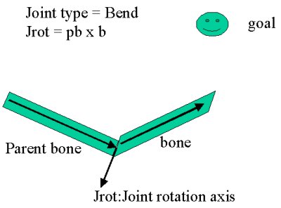 |
 |
| Figure 1. Bend joint axis | Figure 2. Socket joint axis |
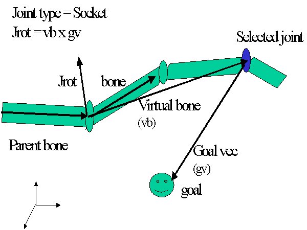
The socket joint has more freedom. It rotates around a plane of
axes sweeping out a cone in the space. For example, in Figure3
below, the shoulder joint allows the upper arm to sweep out a cone of 90
degrees around a horizontal central position. To specify the rotation
axis, we introduce a couple vectors. Define
goal vec = a vector from selected joint to the goal;
virtual bone = a vector from the joint we are examining
to the selected joint.
To see why we want to use the virtual bone instead of the actual bone,
consider this scenrio. Reach out your arm in front of you to
horizon, have your elbow bent and hand tilt down. The goal
is directly above the elbow, and the selected joint is the hand.
If we use the actual upper arm bone to find the shoulder's rotation axis,
we endup bringing the elbow closer to the goal, resulting in the selected
joint moving downward and getting further from the goal.
To reach the goal most efficiently, we want the rotation axis to be
perpendicular to both the goal vec and the virtual bone.
Given we know how far I am from the goal and the most probably rotation
axis, we rotate each bone in hierarchy a little closer to the goal in turn.
The rotation amount is proportional to how far the selected joint is from
the goal. The proportion constant is decided by angles such as the
angle between the bone vector (real bone in Bend or virtual bone in Socket),
the angle between the rotation axis and the bone vector. For example,
when the bone and the the goal vectors are aligned, it means we can't move
any more, so the proportion constant makes sure the rotation amount is
zero in that case. For the rotation amount calculation, I referred
to this
site.
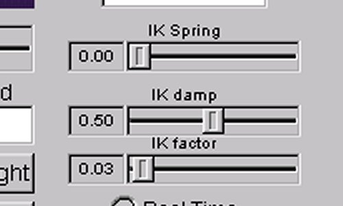
Now that we have defined how to rotate each bone, let's examine the overall iterative process. In every iteration, we move each bone a little, in essence bringing the entire hierachy up to the root a little closer to the goal. To create natural movement, we try to move the bones closer to the selected joint first. For example, if you can reach an object with mere extension of an arm, you are not likely to stand up to reach. In terms of the amount of the movement, we also want to move the bones closer to the selected joint more than the bones that are further away. This naturalness factor is controlled by the damping slider on the user interface. The damping factor specifies the exponential decrease in rotation amount for joints that are far from the selected joint. In the extreme case of damping equal to zero on the slider, rotation amount is multiplied by zero for any joints higher in hirarchy than the selected one, so only the selected bone may move. The Jacobian method does a good job in spreading movements out more globally, here is a hack trying to achieve that effect.
Another effort put into the natural look is the added springyness trying
to bring the joints back to their natural position. One component
of the joint limit specification is the specification of a natural position
vector. For example, the natural vector for the arm points downward.
The natural vector is in line with the minimum energy comfortable position.
In actual implementation, this is done by adding to the goal vector a fraction
of the distance vector from the joint to its natural position. I
have also tried other implementions such as adding a rotation rotating
toward a bone's natural position after calculating the new position, but
those were more complicated and didn't seem to work too well.
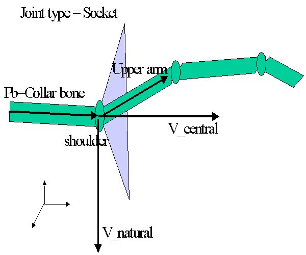 |
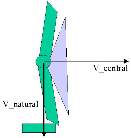 |
| figure 3. Socket joint limit | figure 4.Bend joint limit |
Major Stumble Blocks and limitations
After deciding on rotation axis and the seemingly plausible joint limits specification, I ran into a major stumble block: I had a strange twisting problem. Here is the exe, if you want to recreate the phenomon. As I use quatnion arithematic for applying one rotation on top of another, one possible suspicion is that there are rotation axis drifting through quaternion multiply. A neat hack fix is to figure out the new position using the above method then zero out the quaternion, and store the quaterion encoding rotation going from the plain offset to the new position. But that did not fix the problem. I figured out the cause of the twist problem only very recently. The root cause lies in the virtural bone. The orientation information is lost when we use the virtual bone. Consider the virtual bone between the selected wrist and the bone under examination upper arm, if the elbow is bent quite a bit, the arm limb shapes like a bow and the virtual bone as the string. The rotation axis preserves the orientation of the virtual bone with respect to the parent bone (collar bone in this case). As the actual bone deviates quite a bit from the virtual bone, the orientation is lost and twists result in such cases. So the correct fix is this: decompose any socket joint into a twist followed by a bend joint. A twist is a rotation that uses the parent bone as the rotation axis. The following bending axis is then rotated by the twist angle. Unfortunately, due to implementation issues we won't see the fix in practice.
Other than the major twist tendency , specifying joints limits in the circular cone style is probably not a good idea since some socket don't produce whole range circular motions. For example, the upper leg makes an elliptical cone, i.e. we kick in a bigger range back and forth than sideways.
Antoher thing that I have tried but with no success is moving the root, allowing a pinned down joint (e.g. keep one foot on the floor). The implementation goes like this, summing up the force vectors acting on the root from all the end effectors. EAch force vector is determined by the distance that end effector is from the root, it uses the hooks spring law F= -kx. the hooks constant is proportional to the limb length. The IK solver decides if may try to move the root if the target is definitely out of reach and the pinned down joint may have rom for stretch. Then it tries to move teh root a little according to the summed force direction, and then invoke ik solving on the pinned down joint. If it detects the pinned joint can not reach the goal (the pinned down position) after the root movement, it reverts everything back to before the root movement. The failure of this feature is probably due to haste in implementation.
One feature that is necessary to make it user friendly and easy to implement is to read in the joint limit file. Right now all joint limit specifications are hardwired. If the motion file has different joint names, that joint will not rotate.
The system allows for reading and writing a quaternion bvh(qbvh). This file format is identical to bvh, except that instead of storing Euler rotations, it stores Quaternions. Write qbvh option writes out the interpolated motions only. If you don't want to interpolate but still want to write a qbvh, just key every frame to save the entire motion. Wirte out interpolated motion is useful for motion editing. In the bvh directory, there is an example of an ik'ed animation. The original is a still left leg, and aleg.qbvh is an ik'ed kick.
Here is a picture of the UI.
These are the
ik solver's parameter tweaking sliders.
Here are the
source code.
exe
some bvh
So what have I learned from this project? IK is harder than I
thought. It's neat to see what simple physics can produce. I appreciate
the simplicity of its concepts but I am also curious to see how the systematic
way of solving for constraints works.