This project required us to create a viewer for motion capture data. The viewer was meant to be fully functional and allow a certain degree of motion editing through interpolation.
The program was implemented for IRIX with OpenGL being used to display the graphics. The interface is a simple key based interface.
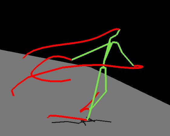
The error vectors are drawn to indicate how far an interpolated motion is from the original motion. The vector is drawn from the end of each End Site of the interpolated skeleton to the End Site of the original skelton.
The keyboard interface allows the user to stop and start the animation, step through the animation frame by frame, toggle euler/quaternion angle representations, set start/stop frame for interpolation, and toggle the display of motion traces. The user can also play the animatio in reverse. The speed of the animation is set according to the input files Frame rate parameter.
Forward kinematics are used to display the skeleton, the motion traces, and the shadow. At the beginning of each frame the kinematics are calculated recurivly through a tree structure which represents the skeleton hierarchy. The locations of the beginning and end of each limb are stored in the tree. Once the forward kinematics are computed and stored, the drawing routines use the information to draw the appropriate lines. Note: the forward kinematics are computed every frame
The motion of the End Sites was stored in a list and drawn according to the motion trace toggle. These lists are cleared when the motion wraps around to the beginning of the motion, or when the motion is reversed.
The user can specify whether interpolations occur between Euler angles or quaternions. The conversions are done on the fly and both representations are finally converted to a rotation matrix to facilitate computations.
The user can also choose to create a keyframe representation of the motion. The default number of keyframes is 20, and the user can adjust this as necessary. The two animations below illustrate the results with the motion from TIP06.BVH. The original sequence of 141 frames was reduced to a set of 20 keyframes through which the motion was interpolated using euler angles. Note that the keyframes appear as quick flashes of bright green, while the error shows up as magenta lines.
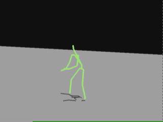 |
Original Motion |
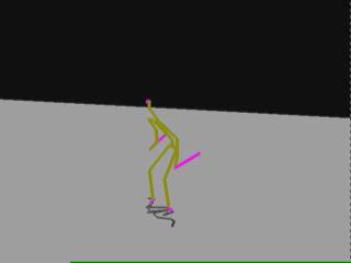 |
Keyframed Motion |
The algorithm is essentially a greedy algorithm. The set of keyframes is initialized to all the frames of animation. At each iteration the error associated with removing each frame is calculated. Then the frame with the smallest error is removed, and the animation though that frame is interpolated. The algorithm works with both Euler angle interpolation and quaternion interpolation.
The error metric used was the sum of the squared Euclidean distance from the interpolated End Sites to the original End Sites.
The figure above illustrates the accumulated error as a function of interpolated frames. The error clearly increases as the number of interpolated frames increases. However, the error for the quaternion interpolation increases at a slower, more even, rate. The accumulated error for Euler anlge interpolation experiences more sudden jumps and grows at a greater rate.